Tuesday, December 27, 2016

Rewiring Project Proceeding

The video below documents the biggest reason I undertook this rewiring project: I wanted to add more signal detectors, but this part of the layout was moved from an earlier location and has several layers of wiring kludges. Eventually, about three years ago, I more or less realized I needed to tear all this out and start over. Around the same time, I started converting to DCC, but things like basic loco decoder installation (and climbing that learning curve) took priority.

Finally a few months ago I got the confidence to rewire this section of the layout. I can't quite give a schedule for completion, because each time I think I'm getting close, I find something else I have to fix, but things are moving along. This video shows the result of some new track and complete replacement of wiring at CP CONN


I spent a good part of my career in the IT field, which has been a good background for starting in DCC. It's just as well that I didn't touch DCC until after I retired, though, because otherwise it would have been too much like work. Documentation is very important.

Digitrax provides some good worksheets that help with this kind of chore. I realized I had to figure out an address scheme for all the stationary switch decoders. Here's the address layout for the section I'm working on:

I think this will pay off down the road.

Tuesday, December 20, 2016

Bachmann E7 Is Out

I noticed on the MB Klein site that the Bachmann E7, announced earlier this year, is in stores:

I can't handle this with my pre-holiday budget, but I want to get one early next year. Like other recent Bachmann diesels, they're reasonably priced, and some have the limited-feature Soundtraxx option. Bachmann paint in recent years is quite good.

The E7 is a good choice, it seems to me. They were built between 1945 and 1949, and, like the Southern example shown, often appeared in the elaborate early streamliner schemes. But by 1952-3, there was a wave of passenger train discontinuances, and a result was that the E7s moved pretty quickly from the top trains, where they were replaced by E8s and E9s, to secondary runs, where they often ran as single units. This is the sort of service I want to run on my layout.

A detail issue is that, like the early F3s, the E7s tended to overheat on some railroads, and they were modified with extra air intakes on the carbody side. But not every railroad did this, or they didn't do it at the same time, in the same way, or on all units. An early publicity photo of NYC E7s shows a set with original air intakes, but photos as of 1949 show the modified side panels. PRR units were also upgraded very quickly.

Looking at photos, though, I see that Burlington, Southern, and Union Pacific units either were never modified or were modified pretty late. The Bachmann models all have the original air intakes, but the photos on the Klein site show variations in Mars lights and numberboards. Apparently on the Soundtraxx versions, the Mars light works on units where the prototype had them.

Looking forward to getting one!

Tuesday, December 13, 2016

T-Track 1.0

I've completed tracklaying and electrical/DCC work on the first four T-Track modules in this project. Some debugging remains to be done, but at this point, operations are reliable, and I'm starting scenery work. Here's a video of the current status:


The section of scenery-in-progress shown on my video is inspired by the Empire Connection, Amtrak's route on the west side of Manhattan. Here's a video (not mine) that will give an idea of what I'm aiming at:

My main focus on this layout will be Amtrak passenger and modern commuter operation. The plan will let me run push-pull trains in particular, at the moment with Kato Metra equipment, but in the near future using Amfleet sets with P42s on each end.

I took these videos in slightly dark conditions to show the lighting effects, which I like.

Tuesday, December 6, 2016

Life-Like 40-foot Boxcar

At a recent swap meet, I discovered a Life-Like 40-foot boxcar lettered for Linde Air Products. I mentioned it in this post. Here's how it was when I found it:

Via the HO-Scale Trains Resource, I found a little more info on these cars. I'm not sure if there's a good history of Life-Like available on the web. They offered crude scenery products around the time I started in HO around 1960. I'm pretty sure they got started with operating models by acquiring the old Varney tooling sometime in the 1960s. By the 1970s they'd moved production to China and were releasing updated paint schemes.

The 40-foot boxcar is crude Varney tooling from the 1950s. The contemporary Athearn 40-foot boxcar is much better in comparison. However, some of the paint schemes on the newer Life-Like cars are appealing.

The problem is that trucks and couplers need to be replaced. Michael Cawdrey, an Australian modeler who follows Guilford in New England, got hold of one of these in the very appealing Maine Central scheme.

Following the photos he's posted on Photobucket, it looks like he finally got stumped by all the upgrades he'd need to do and grounded it with a really good weathering job. If I run into a Maine Central car at a swap (at least, at the right price), I'd pick it up. I see Life Like did BC Rail and Lehigh Valley versions in the late 1970s or early 1980s, and at the right price, I'd probably grab one of these as well -- wish I could hire Mr Cawdrey to weather them, though!

Here I tossed the trucks and plugged the mounting holes in the chassis with pieces of sprue:

You can see that I also added styrene pads to level up mounts for Kadee coupler boxes. I cut off the sprues level with the bolsters and drilled out #50 for 2-56 screws, also mounting the Kadee boxes the same way:

I added weight up to NMRA standards with pennies, stuck on with silicone caulk:

Here is the finished version, lightly weathered to cut the day-glo shine:

These cars actually held a tank inside the boxcar body, but they looked just like 40-foot boxcars. As such, they lasted into the 1980s, though not in the Life-Like paint scheme. You could see thm on Cajon pass up to the end -- here are two I found near Ontario, CA on the SP about 1981:

Tuesday, November 29, 2016

Rewiring, Whew!

The rewiring project is well under way:

There are several subtasks in this phase. One is to remove one DC cab circuit entirely, and replace the other, which had been 22 AWG color coded green and yellow, with 14 AWG DCC cab bus color coded red and black. This will include removing all block toggles from the control panels.

Another task is adding a USB connection from my computer to the layout via an NCE USB interface for JMRI. Here is the USB cable going through the wall into the layout room:

A third task is to replace the control panel toggles that operated Tortoise switch machines with stationary DCC decoders. This will do two things. The first is to allow switches to be thrown at any point on the layout via a handheld DCC controller, rather than having to go to the particular panel with the proper toggle. Here's the old way of doing things:

Neither the block toggles nor the switch toggles will remain when things are finished, though this will take some time. The second advantage will be to use the USB connection to my computer to be able to control switches via a JMRI dispatcher's panel on the computer. (This will only be really useful if I can ever find other operators for the layout.)

I'm also recycling some surplus components removed during rewiring onto the T-Track module project. In addition, I'm using stationary decoders for switches from the start with T-Track.

You can also see an Atlas snap relay, surplus in the rewiring project, that will be controlled by stationary decoder and control signals on the T-track modules.

Monday, November 21, 2016

Looking At The Walthers Mainline SD70ACe

Six-axle EMDs are uncommon in California on the BNSF, even less so in the Los Angeles area. Still, I decided to give the Walthers Mainline SD70ACe a try. These are very reasonably priced, especially for the sound version, and I found one on line for 5% off the discount price on a Veterans Day sale. Here's a shot of the loco out of the box, with couplers installed:

The details are generally good, as is the paint, although the paint doesn't include warning labels. The biggest problem is the bare cab roof:


As delivered, these locos had GPS and antenna domes on the cab roof. Here is a 2014 photo of the prototype 9372 that also shows the warning labels missing from the model's paint:


More recently, PTC antenna arrays have appeared on prototype cab roofs. These vary by railroad and also by date they were installed, and some models have these, while others don't. Here is an MTH SD70ACe that I installed aftermarket PTC antennas on the cab roof:

I'm not sure, though, if the BNSF styles of PTC array are even available as aftermarket parts.

Here is a video I made to compare the lights and sound of the Walthers SD70ACe with my MTH loco, followed by a prototype BNSF SD70ACE:

The Soundtraxx basic sound with the Walthers model doesn't seem to give a choice of horn, but both the MTH and Walthers horns seem close to what you hear in the video. I wish the ditch lights were brighter in both models. I like the fact that function F5 turns the ditch lights on and off on the Walthers model.

Tuesday, November 15, 2016

My History Modeling Signals

I've had signals on my layout ever since I started with HO. I remember being in junior high school and building a signal bridge with balsa strips, washers, and red and green grain of wheat bulbs that I controlled with a DPDTY switch. My more modern evolution begins with the start of this layout project at an earlier home in 1988. I saw an article by Gary D Petersen, "Simplified CTC Signals", in the July 1988 MR. Here is an image from part of a page in that article:


Here is a switch machine block I built following the article:

I've replaced almost all of these on my current layout, when I switched to Tortoises, but this is an example of what could be done with the earlier technology. Notice that I filled in a lot of the space around the machine with silicone calk to keep it from shaking itself out of alignment. Another problem was that the machine also eventually shook loose solder connections.

Here's a photo that includes some of the electronic gear that went under the layout:


And a photo of the very crude CTC machine under construction following the Gary Petersen MR article:

I had a fantasy when we moved to this house of having a CTC board with a dispatcher in another room, but I began to realize how much wire this would require, and I also began to realize that realistically, it's hard to put together an operating group, so I dropped it. However, my layout does have signals:

Here is the electronic equipment that controls this signal.

Tuesday, November 8, 2016

Rewiring -- CP CONN

I've always been interested in signals. My basic concept for my present layout, including the part that was started in the 1980s, was to emulate CTC control points. The way I've gone about it has changed over the years.

The current rewiring project has had its effect. DCC will allow simplification and may eventually let me hook things up to a computerized panel. Once I began to get an idea of how much wire it would take to do something like the CTC panels you read about in the model press and on the web, I realized this wasn't doable for a single builder like me.

However, I eventually worked out a way to put detector and relay panels under the benchwork. This is the one at CP CONN almost exactly three years ago:

These are analog relays and detectors cobbled together with Radio Shack components. the wiring was just being started here, but eventually I got stumped. here's the project as it is after I restarted it today:

The wiring will be neater when the DCC bus replaces the green and yellow color coded block wiring. This and some additional hardware will control this BLMA gantry at CP CONN:

The gantry is temporarily propped up. Logic Rail Technologies has come up with hardware that can control this, used along with some of the detectors and relays shown above.

Those shown are from Dallee Electronics. My oldest are almost 30 years old. I discover I can use them with JMRI computer panels with an interface.

Wednesday, November 2, 2016

T-Track Modules Assembled

I was able to set up a temporary surface for the T-Track modules. Here's a video of them assembled with a Kato Chicago Metra set running:


Tuesday, October 25, 2016

The Rewiring Project Resumes

As I've said, there has been a low-priority rewiring project under way, focusing especially on the oldest part of my layout, where there are undocumented feeders and wire runs, and where solder joints are coming loose. This had me stumped for a year or so, but the T-track project gave me better insights into DCC, the best way to wire it, and the value it adds.
In 2013, I got the NCE entry-level system, a PowerCab. Previously I had two DC walkaround systems, which the maker discontinued not long after DCC came in, and they were wearing out, with replacement parts no longer made. (But they had a 30 year life, no complaints there.) I disconnected one of the DC systems from the block wiring for one side of the DPDT controls and replaced it with the PowerCab.
However, this was giving me only DCC control of locos with decoders. Once I became aware of what stationary decoders can do, I began to realize I can do away with conventional control panels and a lot of confusing wiring, and eventually use a computer screen to control the layout.
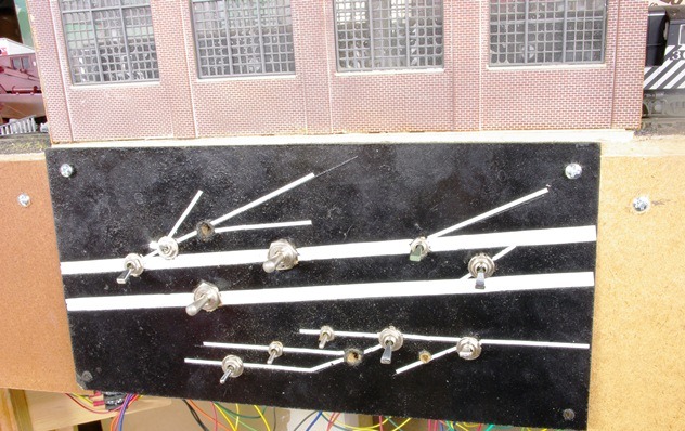
So here's the old wiring. As I said in a previous post, I learned to paste labels and other documentation to terminal strips and so forth, but this was a gradual process, and older parts of the layout don't have this.

As of now, "CAB A" is a former DC walkaround system that has been disabled. The PowerCab was connected to the "CAB B" wiring. Under the current rewiring project, the "CAB B" circuit will be connected to a full DCC bus, for starters on the oldest part of the layout. This will result in 14 gauge wire with a different color code replacing all the green and yellow track circuit wiring, This will take place on a piecemeal basis. Here are some terminal strip panels that had been added but not completed as part of the ongoing rewire project. Here's where this stands:

It will be possible to get rid of all the dangling green and yellow wires. With DCC, there's less wiring, and things can be a lot neater. All the "CAB A" wire, terminal strips. and spade connectors are now surplus and can be recycled, for instance on my T-Track modules:

In honor of the rewiring project, Interstate RS-3 31 pulls a Western Union material car over a stretch of track that will be the first rewired:


Friday, October 21, 2016

More Thoughts On DCC

The oldest part of my layout dates from the late 1980s (almost 30 years, come to think of it). There has been a low-priority rewiring project under way for this oldest section -- overdue, as old solder joints are coming loose. The expanded layout was begun in my current home in 1993, with part of it moved from our old place. This was all pretty much pre-DCC, and by about 2000, DCC was still not really mature -- decoders buzzed and required loco frames to be milled out in many cases.

I started adding DCC to operations in early 2013, and since then have concentrated on installing decoders in locos. Since working on my T-Track layout, I've begun to look at the world of stationary decoders, which is leading me to think hard about computer interface. One thing I've come to realize about my HO layout is that it's pretty much reached the limit of what I can accomplish with traditional block control and separate switch machine wiring. Here's an example of what I'm struggling with:

In contrast, here is equivalent wiring for a full DCC application:

Among other things, I can do away with that whole Masonite panel with the lines and switches on it. This is leading me to rethink the rewiring on my HO layout.

Tuesday, October 18, 2016

T-Track Modules 1.0 Getting Close

My order of additional Unitrack and DCC components arrived, and the pieces are coming together. Here is module 1, top and bottom:

I'm using a trick I figured out in my HO layout, which is to glue documentation next to the DCC and other electrical components so I quickly know what I have and how it's wired months or years down the road. Below is module 2, top and bottom:

This is is the one with the depressed deck that will represent a Chicago grade-separated line. The elevated section is white foam. An industrial siding will go at the top center. I've cut out a circular space in the foam to install a Rapido/RailCrew magnetic uncoupler, which will go in as part of next month's work.

I got enough components to be able to move my NCE PowerCab between the HO layout and the T-Track modules. Here's the first power-up, showing the red LED lit on the fascia:

And here's the first loco to move on the layout, showing its headlights lit under DCC:

The next task that will complete the 1.0 phase will be to program the stationary decoders that control the switches and assemble the four starter modules on a temporary surface to get things running and start scenery.

Wednesday, October 12, 2016

New Camera

I got my Pentax K-7 body in the mail last evening. As I had been hoping, the lens, memory card, and USB connection from the old camera are all compatible, although the K7 is a step up in sophistication from the K2000. This is more or less what I'd meant to do all along, since the K2000, an entry level DSLR, was my first digital camera, although I'd been using SLRs for 40 years. So I was able to upgrade using a used body at a reasonable cost and am now getting used to the incremental changes.

Here's a test shot:

The video capability is new with this camera. I spent a couple of hours figuring out how to take a video, edit it, and upload it. Here's the first test:


Thursday, October 6, 2016

Phase 1 T-track Plan

Here is a rough sketch of the Phase 1 layout plan that I'm putting together with T-trak modules. The track outline is in black, the module borders are in blue.

I'm putting together an order to complete most of the Phase 1 trackwork and electrical components. So far, my experience is encouraging. For me, it's a foray into new principles of layout design, because this layout will be

  • modular
  • easily dismantled and moved
  • reconfigurable
  • expandable
  • with new-generation electrical components and a computer interface via JMRI, programmable
The computer interface and two additional lengthwise modules will be part of a Phase 2. But moving to stationary decoders means switches can be thrown from the DCC hand-held controller, so no permanent control panel is needed. Adding or moving modules means yoiu don't have to change the control panel schematic or do something about control panel switches -- and there's no rat's nest of wiring to redo. As a design principle, I want to keep wiring local to each individual module.

Then at a later time, I can add a computer interface that, with infrared detectors, can control trains for automatic operation.

Wednesday, October 5, 2016

Pentax K2000 RIP

My Pentax K2000 camera expired over about the past two weeks. Here's one of the last photos I shot with it, a boxcar converted to a HEP B unit on the Napa Valley Wine Train:

Here are a couple more last photos, N projects I pulled out of storage. I did these in the late 1970s and early 1980s:

I got the K2000 in 2009. I'm a little miffed that it lasted all of seven years, but then I took thousands of photos with it, so I suppose it paid for itself.

Researching options, I found a used Pentax K-7 body on line, and it looks like I can use the lens from the K2000 with it. The K-7 also shoots video, so I can expand my projects.

Thursday, September 29, 2016

Progress On The T-trak Modules

I painted the front fascia of the lengthwise modules rattle-can black and added the NCE PowerCab interface to the primary one:

The lengthwise module that goes opposite this one, at least in the current scheme of things, is a Masterpiece Modules double wide depressed deck. I cut down the lengthwise faces of the module to go down to the depressed deck. I also took a hint from David Popp and the MR Video Plus T-trak module series and glued pieces of wood inside the end walls to provide a solid surface to attach the Unitrack, since the rest of the track will go on foam.

One of the prototypes I intend to run on these modules, which will focus on modern passenger service, is Chicago Metra. Most modelers who do a Chicago prototype miss a major feature of Chicago: it's a multilevel city. In the 19th century, Chicago raised the level of its city streets above the lake level to avoid flooding, but places where the level wasn't raised are common.

But then between about 1900 and 1930, the city required the railroads to elevate their rights of way in a massive grade separation project. So this is a common sight when you're driving through the city:

(This was taken on Cicero Avenue near the Irving Park station on the Milwaukee Northwest District.) I will build up the fill with foam and add an overpass similar to the one in the picture. This will also be an opportunity to add street furniture.

Thursday, September 22, 2016

Assembling The T-trak Module Kits

I ordered some T-trak module kits from Masterpiece Module Kits. Once the packing is removed, this is how they arrive:

This turns out to be a very high-quality product on good-quality plywood. There's an instructional video on Youtube that is very helpful in assembly. There are a number of value-added features, including predrilled holes for screwing Unitrack sections into place from below -- screws are included for this. In addition to the video, the instructions are detailed and comprehensive, and they give diagrams for how to lay out the Unitrack for common layout designs. The kit is so complete that it includes sandpaper, although you have to supply your own carpenter's glue.

So much thought has gone into this that each module piece has been given a serial number corresponding to each individual module. This is very helpful in keeping the assembly straight and avoiding errors.

A serial number on one of the pieces is shown below:

The pieces are a hammer fit, which is a little fussy until you get used to it, and result in a very robust module. The size and weight make them easy to carry and work on. Below is a completed module, front and back:

With the modules complete, I've begun tracklaying.

The track to the left is the Kato concrete-tie Unitrack with superelevated curves. This is a very nice feature, and I'm surprised that no forums, magazines, or blogs mention it. There are a few Youtibe videos that show it in use, but they're all along the line of living room floor layouts that don't suggest the scenic potential of this track.

Once I got this module this far, I really started to feel encouraged about this project.

Below is tracklaying progress on a lengthwise module:

There will be a double crossover in the lower left and a third main line at the bottom. Finally, here are electronic components going in below this module:

At the upper right is a Digitrax DS52 stationary decoder for the Kato switch machines. A second one will go in as well. Radio Shack terminal strips for track power are in the upper left. My aim is to make each module self-contained for wiring. Again, the ability simply to flip a module and work on the wiring from above is a great advantage.